Coordinate systems
Earth coordinate systems
When defining the configuration space, four coordinate systems are usually involved in target tracking algorithms.
- Geodetic
- Local-tangential East-North-Up (ENU)
- Earth-Centered Earth-fixed (ECEF)
The transformations between the systems exist and are non-linear.
Geodetic coordinates
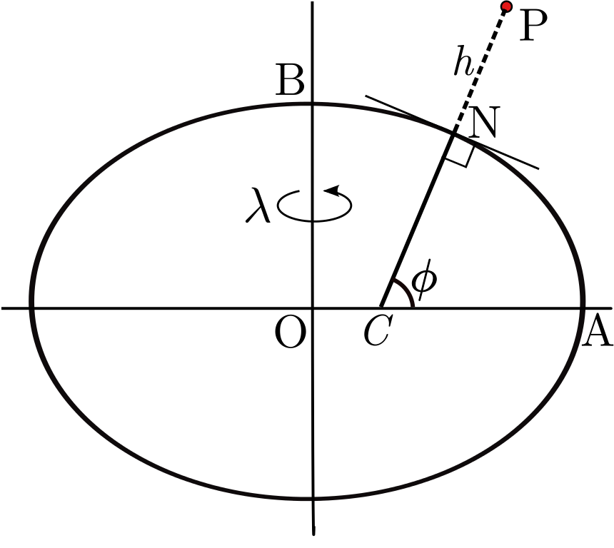
The earth’s surface is approximated by an ellipsoid of revolution of known parameters. The parameters depend on the datum of choice. In the scope of this chapter, the selected datum is the WGS 84. Locations near the surface are described in terms of latitude, longitude, and height $(\phi, \lambda, h)^T$.
Local-tangential - ENU
The local tangential plane coordinates, are based on the local vertical direction and the earth’s axis of rotation.
Two variants exist, the selection of which is a matter of convention but leads to slightly different state vectors in tracking applications.
- East, North, Up (ENU)
- North, East, Down (NED)
The local-tangential east-north-up plane is the rectangular coordinate system determined by fitting a tangential plane to the surface of the earth at some reference point $[X_0,Y_0,Z_0]$. The reference point is the origin of the frame.
Such a system is convenient in the context of tracking nearby ships because the tracking problem can be reduced to tracking a target on a two-dimensional plane.
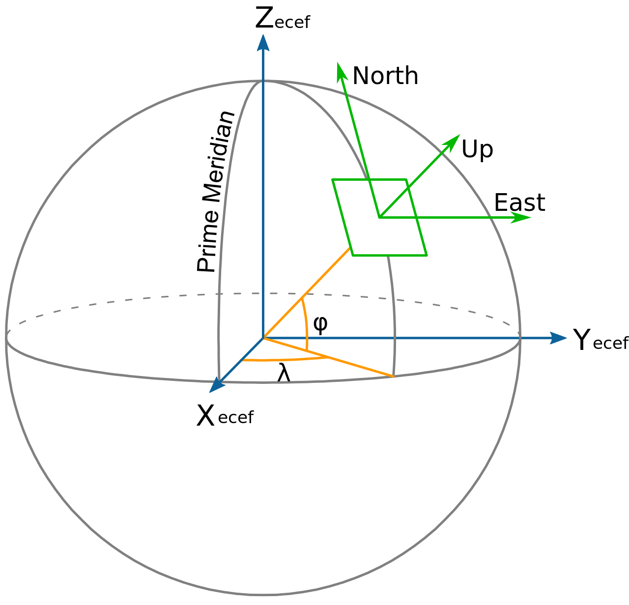
Earth Centered Earth-fixed (ECEF)
ECEF is a cartesian coordinate system $[X,Y,Z]^T$ with its origin placed at the earth’s center of mass, hence the naming convention. It is a rotating system as the z-axis is pointing through true north and the x-axis intersects the earth’s sphere at $[\phi,\lambda]^{T} = [0,0]^{T}$.
Transformations
There is a need to define transformations between different coordinate systems.
Geodetic to ECEF
GPS measurements usually arrive in geodetic coordinates, where as tracking is usually performed in the local tangential plane of the own-ship.
The transformation between these two systems requires an intermediate transformation from geodetic $(\phi,\lambda,h)$ to ECEF $(X,Y,Z)$ coordinates.
$$\begin{align*} X &=(N+h)cos\lambda cos\phi \\ Y &= (N+h)cos\lambda sin\phi \\ Z &= [N(1-e^2)+h] sin\lambda \end{align*}$$
ECEF to ENU
Given a reference point in Geodetic $[\phi_0,\lambda_0]$ and the corresponding ECEF $[X_0,Y_0,Z_0]$ coordinates, then any other point’s ECEF coordinates $[X,Y,Z]$ can be converted to local tangential plane coordinates $[x,y,z]$ using the following transformation
$$ \begin{bmatrix} x\ y\ z \end{bmatrix}= \mathcal{L}\left(\begin{bmatrix} X\ Y\ Z \end{bmatrix} - \begin{bmatrix} X_0\ Y_0\ Z_0 \end{bmatrix}\right) $$
where $\mathcal{L}$ is a function of the reference point $[\phi_0,\lambda_0,h_0]$
$$ \mathcal{L} = \begin{bmatrix} -sin\phi_0 & cos\phi_0 & 0 \\ -sin\lambda_0cos\phi_0 & -sin\lambda_0sin\phi_0 & cos\lambda_0\\ cos\lambda_0 cos\phi_0 & cos\lambda_0 sin\phi_0 & sin\lambda_0 \end{bmatrix} $$
Ship coordinate systems
To describe the position and orientation of a ship, one can use the following orthogonal coordinate systems:
- NED/ENU, $\{n\} , \{e\}$
- Body-fixed, $\{b\}$
- Seakeeping, $\{s\}$
- Tracking coordinates, $\{t\}$
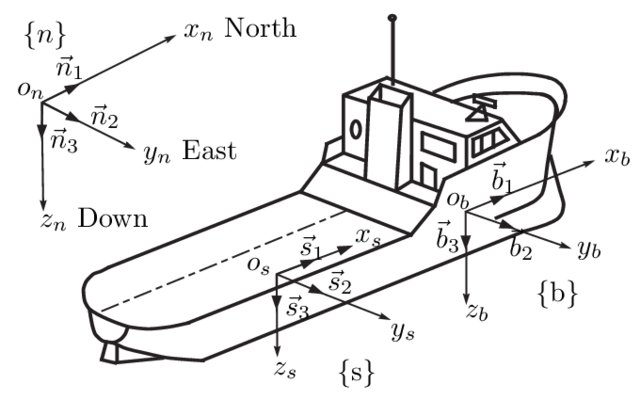
Body fixed coordinate system
This system is fixed to the hull of a vessel. The x-axis pointing towards the bow, y-axis point starboard and z-axis pointing downwards completing the orthogonal system. The origin of the system is usually the origin of the principal axes of inertia, which simplifies the solution of the dynamical equations of motion for the body.
Seakeeping coordinate system
The seakeeping frame follows the average speed of the vessel. As such, the system is fixed to the ship’s equilibrium state, which is defined by the average speed and heading. The positive x-axis is pointing towards the forward velocity vector, the y-axis pointing starboard and the z-axis pointing down. The origin of the system is selected so that the z-axis is pointing through its mean center of mass, and the x-y plane coincides with the mean free water surface.
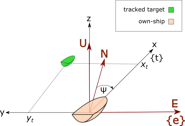
Tracking coordinates system
For the shake of simplicity, one can define the tracking coordinates system $\{t\}$. The origin of the tracking system coincides with the origin of the seakeeping coordinate system of the own-ship. The x-axis is pointing in the heading direction of the own-ship, the y-axis is pointing port, and the z-axis up to complete a dextral orthogonal system. The x-y axes are always coplanar to the East North plane and since this is an equilibrium coordinate system, the coordinates of a tracked target in this system do not depend on the roll or pitch angles of the own-ship. Thus the configuration space for the tracking problem is reduced in tracking along two dimensions.
Purpose of using different coordinate systems
Both the motion and the measurement model equations depend on the coordinate system of choice. Sensor measurements from a radar usually arrive in the sensor’s local spherical system, where as the GPS measurements either for the own-ship or for other vessels arrive in the geodetic system. It is convenient to consider that all floating targets move on the same plane, thus to express a target’s motion model w.r.t the own-ship’s local tangential plane.
Since the local sensors like the radar and the cameras are rigidly attached to the body-frame, it is important to consider the transformations from the body coordinate system to the own-ship’s equilibrium coordinate system.
Transformations
From ENU to tracking coordinates
If the origin of the ENU system is selected to coincide with the origin of the own-ship’s tracking coordinates origin, and $\psi$ is the heading angle of the own-ship from the North direction, then the transformation from ENU, to the own-ship’s tracking coordinates is
$$\begin{bmatrix} x \\ y \\ z \end{bmatrix}_{\text{{t}}} = R_{z}(\frac{\pi}{2}-\psi) \begin{bmatrix} E \\ N \\ U \end{bmatrix}_{\text{{e}}} $$
where
$$ R_{z}(\theta)=\begin{bmatrix} cos\theta &-sin\theta &0\\ sin\theta &cos\theta &0 \\ 0 &0 &1 \end{bmatrix} $$
Purpose of using different coordinate systems
Both the motion and the measurement model equations depend on the coordinate system of choice.
Sensor measurements from a radar usually arrive in the local tangential system, where as the GPS measurements either for the own-ship or for other vessels arrive in the geodetic system.
It is convenient thus to express a target’s motion model w.r.t the local tangential & body fixed frame, since the local sensors like the radar and the cameras are rigidly attached to the body-frame.
This simplifies the measurement models for local sensors, nevertheless working in the local tangential plane induces errors when one has to use models that depend on the earth’s curvature like the AIS.
Dimitrios Dagdilelis
ML/AI Engineer
Hey there, I enjoy making machines observe the world. If you have something interesting to share, there is no better time that now, connect with me and lets discuss.